I see it has been a couple of months since I wrote anything here. Time flies when you're having fun. Blogging has had to take a back seat to both workbench building and a couple of trips to America. More about one of them in a later post. (As a teaser, I can mention that it is about WIA 2011.) Anyway, time to continue documenting the build of my Roubo-inspired workbench. Unfortunately I have been a bit bad at taking photos along the way.
Once the top was more or less finished, I started on the base. It consists of four legs and four stretchers that are joined to the legs with mortise and tenon joints. I made the tenons by simply gluing two pieces together, a short one and a long one, and letting the part that stuck out become the tenon. On the legs I first cut a kerf on the table saw to clearly define the shoulder of the tenon.
Then I milled the tenons on the legs on the spindle moulder. As usual with machine work, setting up the job takes ten times as long as doing it, which is one of the reasons I use hand tools more often than machines when I have a choice.
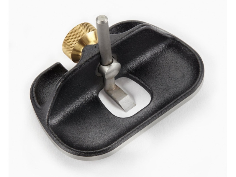
The next step was to lay out on the legs where the mortises for the stretchers should go, and to rout them out. I used a hand-held router with a guide bush and a Festool FS600 routing template. A long 16 mm bit helped reach all the way to the bottom of the mortise. The corners were cleaned up with a sharp chisel and a mallet.
The long front stretcher has a profile for the so-called “deadman” I have written about before. To get some exercise and avoid setting up an angled rip cut on the table saw, I planed it with my Bridge City HP6a with two side fences. It went surprisingly quickly and easily, even though I could not take shavings as thick as I wanted, as I got tear-out in a couple of places where the grain changes direction.

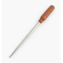
After dry-fitting all the parts and seeing that the joints were reasonably tight and neat, I drilled holes for pegs in the legs, then marked and drilled holes in the tenons with a slight offset (about 3 mm), so that 10 mm pegs would lock the stretcher tenons and help pull the joints tight without having to use clamps. I tested the joints with a tapered steel pin, a drawbore pin, which pulls the joint tight.
The method is called drawboring and gives a strong joint that holds even if the glue gives way over time.
Once the base was glued up and drawbored, I cut off the pegs and planed everything neat and flush. With the help of a teenager recruited by force, the base was turned upside down onto the underside of the benchtop and the mortises in the top were marked out. After more routing and chopping, the legs could be drawbored into the top, and the bench is almost complete.
After a heroic lift of the bench down onto the floor, again with the help of my son, I could plane the legs flush with the front edge of the top. At the back there is a small difference, but it doesn't matter. I don't intend to use the back of the bench to clamp any workpiece against the legs and top. In addition, I made the mortises for the rear legs in the top slightly larger than the tenons to allow for the seasonal movement of the top.
After yet another hefty lift, this time SWMBO also had to lend a hand, the bench stood on all four legs for the first time! A sweaty planing session with my beloved Bedrock 608 made the top of the bench flat as well. All edges got a small chamfer planed freehand with a block plane, and the bench is starting to look finished. What remains is to finish the front and end vices and to drill some holes for bench dogs and holdfasts.
Previous part: The Router Plane to the Rescue! Continued: Even More Almost Done!
Share this content